Statistical Process Monitoring
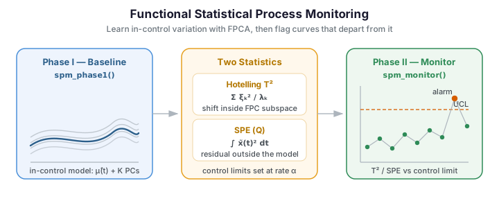
Statistical Process Monitoring (SPM) extends the classical Shewhart control chart to functional data. When the quantity under surveillance is a whole curve -- a spectral profile, a temperature trajectory, a wafer-thickness scan -- collapsing it to a scalar summary and charting that summary throws away most of the information about how the curve is shaped. Functional SPM keeps the curve intact: it learns a low-dimensional model of in-control variation with FPCA, then measures how far each new curve departs from that model. The workflow has two phases:
- Phase I -- Estimate the in-control distribution from historical "good" data and compute control limits at a false-alarm rate \(\alpha\).
- Phase II -- Project each incoming observation onto the learned subspace and check whether its \(T^2\) or SPE statistic exceeds the limits; an alarm fires on a crossing.
When to reach for functional SPM
| Situation | Approach |
|---|---|
| A single functional characteristic per unit | spm_phase1 + spm_monitor (this page) |
| Small, slow drifts you want to catch early | EWMA / run rules -- see advanced monitoring |
| A fault confined to a short sub-interval | slice the domain -- see profile & partial monitoring |
| You need to know why a point alarmed | per-PC contributions -- see advanced monitoring |
This page covers the core two-phase workflow. The advanced and profile / partial pages build on the exact same Phase I model for drift-sensitive charts, fault diagnosis, and localised monitoring.
Concepts
FPCA-based monitoring
Each curve \(x_i(t)\) is centered by subtracting the mean \(\hat\mu(t)\) and projected onto the first \(K\) functional principal components, yielding a score vector \(\boldsymbol\xi_i \in \mathbb{R}^K\). Two complementary statistics capture different kinds of departure:
| Statistic | What it measures | Formula |
|---|---|---|
| Hotelling \(T^2\) | Systematic shift in the FPC subspace | \(T^2 = \sum_{k=1}^{K} \xi_k^2 / \lambda_k\) |
| SPE (Q) | Residual variation outside the subspace | \(\mathrm{SPE} = \int [\tilde x(t)]^2 \, dt\) where \(\tilde x\) is the reconstruction residual |
Control limits for both are estimated from the Phase I data so that the in-control false-alarm rate is approximately \(\alpha\).
The figure below shows a Phase I reference sample (grey) together with a Phase II stream that contains two kinds of injected faults: a set of amplitude-inflated curves (which shift the \(T^2\) statistic inside the FPC subspace) and a set of oscillatory curves carrying high-frequency structure the model cannot reconstruct (which inflates the SPE residual).
The amplitude fault (orange) stays the same shape as the reference cloud but is scaled up, so it lives inside the FPC subspace and will surface on the \(T^2\) chart. The oscillatory fault (red) adds high-frequency wiggle the low-rank model cannot represent; it barely shifts the scores yet leaves a large reconstruction residual, so it will surface on the SPE chart instead. This is exactly why the two statistics are charted together.
Phase I -- estimating the baseline
import numpy as np
from fdars import Fdata
from fdars.simulation import simulate
from fdars.spm import spm_phase1

# Generate 80 in-control curves on a 100-point grid
argvals = np.linspace(0, 1, 100)
fd_ic = Fdata(simulate(80, argvals, n_basis=5, seed=1), argvals=argvals)

# Phase I estimation (3 components, alpha = 0.05)
p1 = spm_phase1(fd_ic.data, fd_ic.argvals, ncomp=3, alpha=0.05)
spm_phase1 returns a dictionary with the following keys:
| Key | Shape | Description |
|---|---|---|
t2 |
(n,) |
\(T^2\) statistic for every Phase I observation |
spe |
(n,) |
SPE statistic for every Phase I observation |
t2_limit |
scalar | Upper control limit for \(T^2\) |
spe_limit |
scalar | Upper control limit for SPE |
mean |
(m,) |
Estimated mean function \(\hat\mu(t)\) |
loadings |
(m, ncomp) |
FPCA rotation matrix (eigenfunctions) |
weights |
(m,) |
Integration weights for the inner product |
eigenvalues |
(ncomp,) |
Eigenvalues \(\lambda_1, \dots, \lambda_K\) |
Choosing ncomp
Retaining the right number of components balances two failure modes: too few and genuine
modes of variation leak into the residual, making the SPE chart over-sensitive; too many
and noise dimensions inflate the \(T^2\) chart. select_ncomp turns the Phase I eigenvalues
into a recommendation under one of three classic criteria:
import numpy as np
from fdars.simulation import simulate
from fdars.spm import spm_phase1, select_ncomp

argvals = np.linspace(0, 1, 100)
p1 = spm_phase1(np.asarray(simulate(120, argvals, n_basis=6, seed=1)),
                argvals, ncomp=6, alpha=0.05)
eig = np.asarray(p1["eigenvalues"])

print("eigenvalues:", np.round(eig, 3))
print("cumulative_variance (95%):", select_ncomp(eig, "cumulative_variance", 0.95))
print("kaiser (eig > mean)      :", select_ncomp(eig, "kaiser"))
print("elbow (scree bend)       :", select_ncomp(eig, "elbow"))
The three rules need not agree, and that disagreement is informative: here the eigenvalues decay quickly, so the elbow and Kaiser rules keep a lean model while the 95%-variance rule holds a couple more components to mop up residual signal. Read them as a bracket -- pick within the range they span rather than trusting any single number.
The scree plot below makes the trade-off visible: the bars show each component's share of the total variance, and the orange curve accumulates it. The 95% line is crossed at the component the "cumulative_variance" rule selects.
import numpy as np
from docs_fig import fig, render
from fdars.simulation import simulate
from fdars.spm import spm_phase1, select_ncomp

argvals = np.linspace(0, 1, 100)
p1 = spm_phase1(np.asarray(simulate(120, argvals, n_basis=6, seed=1)),
                argvals, ncomp=6, alpha=0.05)
eig = np.asarray(p1["eigenvalues"])
cum = np.cumsum(eig) / eig.sum()
k = np.arange(1, len(eig) + 1)
kc = select_ncomp(eig, "cumulative_variance", 0.95)

f, ax = fig()
ax.bar(k, eig / eig.sum(), color="#3f51b5", alpha=0.7)
ax2 = ax.twinx()
ax2.plot(k, cum, "o-", color="#e8710a", label="cumulative")
ax2.axhline(0.95, color="#dc3545", ls="--", lw=1, label="95% threshold")
ax2.axvline(kc, color="#6c757d", ls=":", lw=1)
ax.set(xlabel="principal component", ylabel="proportion of variance")
ax2.set_ylabel("cumulative variance")
ax2.legend(loc="center right")
ax.set_title(f"Scree plot — the 95% rule keeps K={kc} components")
print(render(f))
Almost all of the variance is packed into the first two or three modes, so a compact model captures the in-control behaviour faithfully and the SPE chart is left to police everything the model cannot explain.
method |
Rule | When it helps |
|---|---|---|
"cumulative_variance" |
Smallest \(K\) reaching threshold of total variance (default 0.95) |
The general-purpose default |
"kaiser" |
Keep components with eigenvalue above the mean | Quick, threshold-free screen |
"elbow" |
Locate the bend in the scree curve | When variance is concentrated in a few modes |
When in doubt, keep one more
Retaining slightly more components is the safer error: a missed mode of variation surfaces as a harder-to-interpret SPE alarm that a \(T^2\) chart could have localised.
Phase II -- monitoring new observations
from fdars.spm import spm_monitor

# Simulate 20 new in-control observations + 10 faulty ones
data_new_ic = simulate(20, argvals, n_basis=5, seed=2)

# Inject a mean shift into the last 10 curves
data_fault = simulate(10, argvals, n_basis=5, seed=3) + 2.0
fd_new = Fdata(np.vstack([data_new_ic, data_fault]), argvals=argvals)

# Monitor
p2 = spm_monitor(
    mean=p1["mean"],
    loadings=p1["loadings"],
    weights=p1["weights"],
    eigenvalues=p1["eigenvalues"],
    t2_limit=p1["t2_limit"],
    spe_limit=p1["spe_limit"],
    new_data=fd_new.data,
    argvals=fd_new.argvals,
)
The returned dictionary contains:
| Key | Shape | Description |
|---|---|---|
t2 |
(n_new,) |
\(T^2\) for each new observation |
spe |
(n_new,) |
SPE for each new observation |
t2_alarm |
(n_new,) bool |
True where \(T^2\) exceeds the limit |
spe_alarm |
(n_new,) bool |
True where SPE exceeds the limit |
# How many faults were caught?
n_t2_alarms = int(p2["t2_alarm"].sum())
n_spe_alarms = int(p2["spe_alarm"].sum())
print(f"T2 alarms: {n_t2_alarms}, SPE alarms: {n_spe_alarms}")
Hotelling \(T^2\) from scores
spm_monitor returns the \(T^2\) / SPE statistics and alarm flags, but not the raw FPC
scores. When you need the scores themselves -- to feed an EWMA chart, to break \(T^2\) down
by component, or to compute \(T^2\) by hand -- project the centered curves onto the Phase I
loadings. With integration weights \(w(t)\) the score of curve \(i\) on component \(k\) is
which in NumPy is simply ((X - mean) * weights) @ loadings. Passing the result to
hotelling_t2 reproduces spm_monitor's internal \(T^2\) to machine precision:
import numpy as np
from fdars.simulation import simulate
from fdars.spm import spm_phase1, spm_monitor, hotelling_t2

argvals = np.linspace(0, 1, 80)
p1 = spm_phase1(np.asarray(simulate(120, argvals, n_basis=5, seed=1)),
                argvals, ncomp=3, alpha=0.05)
new = np.asarray(simulate(20, argvals, n_basis=5, seed=2))

# recover scores by projection, then compute T2 directly
scores = ((new - np.asarray(p1["mean"])) * np.asarray(p1["weights"])) @ np.asarray(p1["loadings"])
t2_manual = np.asarray(hotelling_t2(scores, np.asarray(p1["eigenvalues"])))

# compare against the monitor's own T2
p2 = spm_monitor(mean=p1["mean"], loadings=p1["loadings"], weights=p1["weights"],
                 eigenvalues=p1["eigenvalues"], t2_limit=p1["t2_limit"],
                 spe_limit=p1["spe_limit"], new_data=new, argvals=argvals)
print("scores shape           :", scores.shape)
print("max |manual - monitor| :", np.max(np.abs(t2_manual - np.asarray(p2["t2"]))))
The \(T^2\) statistic itself is just a Mahalanobis distance in score space,
\(T^2_i = \sum_k \xi_{ik}^2 / \lambda_k\). hotelling_t2(scores, eigenvalues) computes it for
any score matrix you already have, whether from fdars FPCA or an external decomposition.
Full worked example
The script below ties everything together: simulate in-control data, run Phase I, introduce a fault, monitor in Phase II, and visualize the control chart.
import numpy as np
from fdars import Fdata
from fdars.simulation import simulate
from fdars.spm import spm_phase1, spm_monitor

# ── 1. Simulate in-control data ──────────────────────────────
argvals = np.linspace(0, 1, 100)
fd_ic = Fdata(simulate(100, argvals, n_basis=5, seed=10), argvals=argvals)

# ── 2. Phase I ───────────────────────────────────────────────
p1 = spm_phase1(fd_ic.data, fd_ic.argvals, ncomp=3, alpha=0.05)
print(f"T2 limit : {p1['t2_limit']:.3f}")
print(f"SPE limit: {p1['spe_limit']:.3f}")

# ── 3. Simulate Phase II data (in-control + fault) ──────────
data_ok  = simulate(30, argvals, n_basis=5, seed=20)
data_bad = simulate(20, argvals, n_basis=5, seed=30) + 3.0  # mean shift
fd_new = Fdata(np.vstack([data_ok, data_bad]), argvals=argvals)

# ── 4. Phase II monitoring ───────────────────────────────────
p2 = spm_monitor(
    mean=p1["mean"],
    loadings=p1["loadings"],
    weights=p1["weights"],
    eigenvalues=p1["eigenvalues"],
    t2_limit=p1["t2_limit"],
    spe_limit=p1["spe_limit"],
    new_data=fd_new.data,
    argvals=fd_new.argvals,
)

# ── 5. Report ────────────────────────────────────────────────
obs_ids = np.arange(1, len(fd_new) + 1)
alarm_idx = obs_ids[p2["t2_alarm"] | p2["spe_alarm"]]
print(f"Alarm observations: {alarm_idx}")

# ── 6. Visualize (optional, requires matplotlib) ─────────────
try:
    import matplotlib.pyplot as plt

    fig, axes = plt.subplots(2, 1, figsize=(10, 6), sharex=True)

    axes[0].plot(obs_ids, p2["t2"], "o-", markersize=3)
    axes[0].axhline(p1["t2_limit"], color="red", linestyle="--", label="UCL")
    axes[0].set_ylabel("Hotelling T²")
    axes[0].legend()

    axes[1].plot(obs_ids, p2["spe"], "o-", markersize=3)
    axes[1].axhline(p1["spe_limit"], color="red", linestyle="--", label="UCL")
    axes[1].set_ylabel("SPE (Q)")
    axes[1].set_xlabel("Observation index")
    axes[1].legend()

    fig.suptitle("FPCA-based Control Charts")
    plt.tight_layout()
    plt.savefig("spm_control_chart.png", dpi=150)
    plt.show()
except ImportError:
    pass
Control charts
Running the workflow above on the two-fault Phase II stream produces the pair of control charts below. Each point is one observation; points below the upper control limit (dashed) are in-control (indigo), those above are flagged (red). The \(T^2\) chart catches the amplitude faults, while the SPE chart catches the oscillatory faults the FPC subspace cannot reconstruct -- together they cover both failure modes.
The two charts are complementary detectors. The first 24 observations sit comfortably under both limits; the amplitude faults spike the top (\(T^2\)) chart because their inflated scores are large Mahalanobis distances, while the oscillatory faults spike the bottom (SPE) chart because their unmodelled wiggle lands in the residual. Neither chart alone would have caught both fault families -- the reason functional SPM always reads \(T^2\) and SPE side by side.
Performance note
Both spm_phase1 and spm_monitor delegate all linear algebra to Rust. Phase I on 500 curves of length 200 typically completes in under 10 ms.
How fast does the chart react? (ARL)
A control limit is a compromise between false alarms and detection speed, and the standard currency for that trade-off is the average run length (ARL): the expected number of observations charted before an alarm fires. The in-control ARL\(_0\) is how long the chart runs between false alarms; for an independent stream tripping with per-point probability \(\alpha\) it is the mean of a geometric distribution,
so a 3-sigma limit (\(\alpha = 0.0027\)) targets ARL\(_0 \approx 370\). The out-of-control
ARL\(_1(\delta)\) measures how quickly a shift of size \(\delta\) is caught; a good chart drops
ARL\(_1\) steeply as \(\delta\) grows while holding ARL\(_0\) high. arl0_t2 and arl1_t2
estimate both by Monte-Carlo simulation from the Phase I eigenvalues:
import numpy as np
from docs_fig import fig, render
from fdars.simulation import simulate
from fdars.spm import spm_phase1, arl0_t2, arl1_t2

argvals = np.linspace(0, 1, 60)
p1 = spm_phase1(np.asarray(simulate(150, argvals, n_basis=5, seed=1)),
                argvals, ncomp=3, alpha=0.0027)          # 3-sigma design
eig, ucl = np.asarray(p1["eigenvalues"]), float(p1["t2_limit"])

arl0 = arl0_t2(eig, ucl, n_simulations=3000, seed=1)["arl"]
deltas = np.linspace(0.0, 2.5, 8)
arls = [arl1_t2(eig, ucl, np.array([d * np.sqrt(eig[0]), 0.0, 0.0]),
                n_simulations=3000, seed=1)["arl"] for d in deltas]

f, ax = fig()
ax.plot(deltas, arls, "o-", color="#3f51b5", label="ARL$_1$ (shift on PC1)")
ax.axhline(arl0, color="#dc3545", ls="--", lw=1, label=f"in-control ARL$_0 \\approx$ {arl0:.0f}")
ax.set(xlabel="mean shift along PC1 (× standard deviation)",
       ylabel="average run length", yscale="log",
       title="Detection speed vs. fault size")
ax.legend()
print(render(f))
The curve is the chart's operating characteristic. At zero shift the ARL matches the design target of roughly 370 -- confirming the limit delivers the intended false-alarm rate -- and it falls by more than an order of magnitude as the shift approaches two standard deviations, where a fault is caught within a handful of observations. Faults smaller than about one standard deviation still take many samples to surface, which is precisely the regime where the EWMA charts on the advanced page pay off.
The figure below previews that pay-off. A slow linear drift is fed to Phase II; the raw \(T^2\) (pale) jitters below its limit and only trips late, while the EWMA-smoothed \(T^2\) accumulates the drift and crosses its limit noticeably earlier.
import numpy as np
from docs_fig import fig, render
from fdars.simulation import simulate
from fdars.spm import spm_ewma, spm_phase1, spm_monitor

argvals = np.linspace(0, 1, 70)
train = np.asarray(simulate(120, argvals, n_basis=5, seed=1))
seq = np.asarray(simulate(40, argvals, n_basis=5, seed=2)) \
      + np.linspace(0, 1.8, 40)[:, None]                     # gradual ramp drift

ew = spm_ewma(train, seq, argvals, ncomp=3, alpha=0.01, lam=0.2)
p1 = spm_phase1(train, argvals, ncomp=3, alpha=0.01)
p2 = spm_monitor(mean=p1["mean"], loadings=p1["loadings"], weights=p1["weights"],
                 eigenvalues=p1["eigenvalues"], t2_limit=p1["t2_limit"],
                 spe_limit=p1["spe_limit"], new_data=seq, argvals=argvals)

obs = np.arange(1, 41)
f, ax = fig()
ax.plot(obs, np.asarray(p2["t2"]),  color="#c7cbe0", lw=1, marker="o", ms=3, label="raw $T^2$")
ax.plot(obs, np.asarray(ew["t2"]), color="#3f51b5", lw=1.6, marker="o", ms=3,
        label="EWMA $T^2$ (λ=0.2)")
ax.axhline(float(ew["t2_limit"]), color="#e8710a", ls="--", lw=1.2, label="EWMA limit")
ax.set(xlabel="observation index", ylabel="$T^2$",
       title="EWMA reacts to a slow drift sooner than the raw chart")
ax.legend(loc="upper left")
print(render(f))
Smoothing trades a little detection speed on large sudden shifts for a large gain on gradual ones -- exactly the small-drift regime the raw chart struggles with. The advanced page covers choosing the smoothing weight \(\lambda\) and the matching EWMA control limit in full.
See also
The two-phase workflow above is the foundation; the companion pages extend it without changing the Phase I model:
- Advanced Statistical Process Monitoring -- EWMA charts for slow drifts, Nelson / Western Electric run rules, Monte-Carlo ARL analysis, and per-PC contribution diagnosis to locate the mode of variation behind an alarm.
- Profile and Partial-Domain Monitoring -- restrict the chart to a critical sub-interval to catch localised faults, and monitor curves that are only partially observed.
Method coverage in fdars Python
The Rust core exposes the core two-phase workflow (spm_phase1, spm_monitor),
the individual chart statistics (hotelling_t2, t2_control_limit,
spe_control_limit, ewma_scores), one-call EWMA and CUSUM charts (spm_ewma,
spm_cusum), distribution-free robust limits (t2_limit_robust, spe_limit_robust),
the run-rule and contribution diagnostics
(nelson_rules, western_electric_rules, t2_pc_contributions,
t2_pc_significance), and the Monte-Carlo ARL estimators (arl0_t2, arl1_t2,
arl0_spe, arl0_ewma_t2). A few techniques shown in the R vignettes -- MEWMA/AMEWMA,
iterative Phase I cleaning, and multivariate FPCA -- do not yet have a dedicated Python
binding; the pages here show how to reproduce the most common of the rest (EWMA, CUSUM,
run rules, partial-domain charts) directly from the exposed primitives.
References
- Colosimo, B. M., & Pacella, M. (2010). A comparison study of control charts for statistical monitoring of functional data. International Journal of Production Research, 48(6), 1575–1601.
- Hotelling, H. (1947). Multivariate quality control, illustrated by the air testing of sample bombsights. In C. Eisenhart, M. W. Hastay, & W. A. Wallis (Eds.), Techniques of Statistical Analysis (pp. 111–184). McGraw-Hill.
- Jackson, J. E., & Mudholkar, G. S. (1979). Control procedures for residuals associated with principal component analysis. Technometrics, 21(3), 341–349.
- Ramsay, J. O., & Silverman, B. W. (2005). Functional Data Analysis (2nd ed.). Springer.
- Grasso, M., Colosimo, B. M., & Pacella, M. (2014). Profile monitoring via sensor fusion: the use of PCA methods for multi-channel data. International Journal of Production Research, 52(20), 6110–6135.